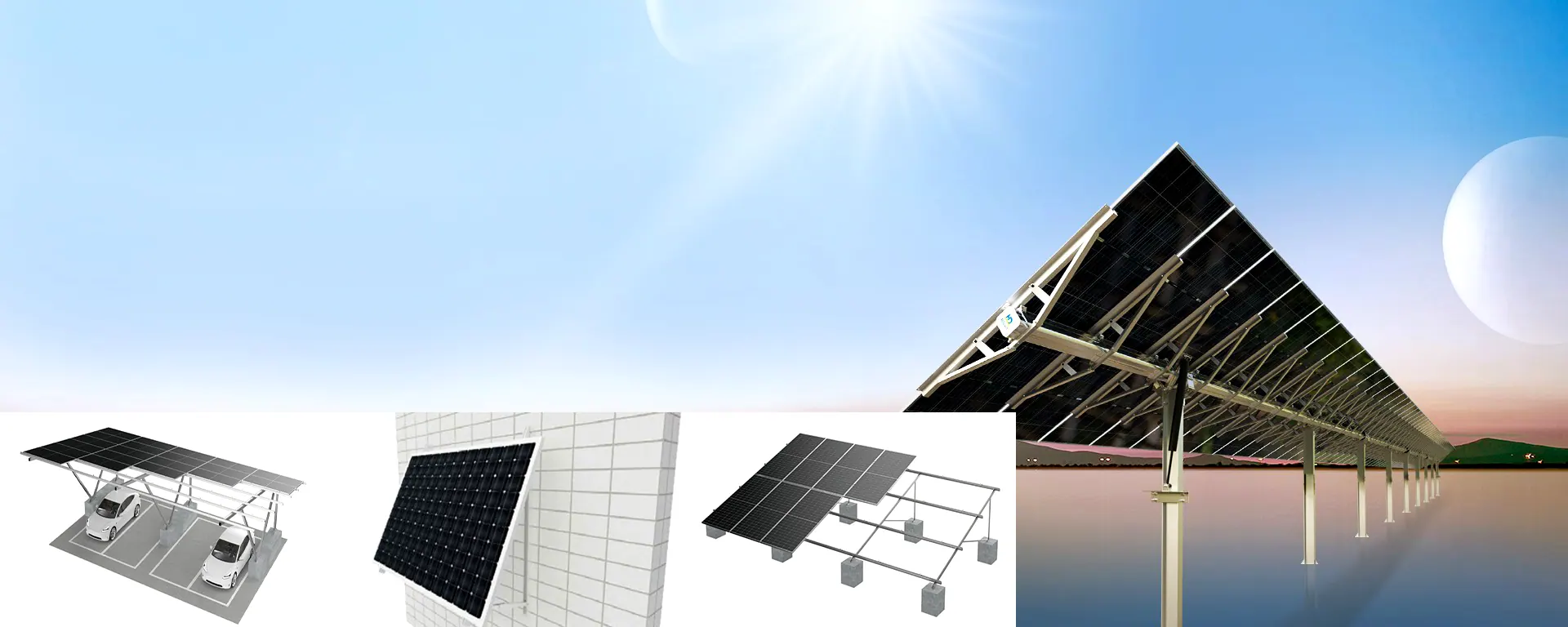
The mounting families at a glance
A solar mounting system is chosen by the interface it has to attach to and the load path it has to create - not by preference. In practice that produces nine commercial families: pitched-roof hook and rail systems, metal-roof clamp systems, ballasted flat-roof systems, penetrating flat-roof systems, fixed-tilt ground structures, driven-pile foundations, ground-screw foundations, carport canopies and single-axis trackers, with floating and balcony systems as two further specialised branches. Get the family right first, and the specification, the bill of materials and the installation method follow logically.
This guide is the hub for that first decision. Each section explains what the family is, what governs its design, where it fits and where it usually does not, with links to the matching Apex product family and to the deeper guide for that topic.
| Family | Site interface | Typical tilt | Usually chosen when |
|---|---|---|---|
| Pitched-roof hooks and rails | Tile, slate, shingle over rafters or battens | Follows the roof, about 5-45 deg | Residential and small commercial pitched roofs |
| Metal-roof clamps and mini rails | Trapezoidal sheet, standing seam, purlins | Flush to about 0-15 deg | Factory, warehouse and agricultural sheds |
| Ballasted flat roof | Membrane or concrete deck, non-penetrating | About 5-15 deg | Roof has load reserve and penetrations are restricted |
| Penetrating flat roof | Anchored into deck or structural frame | About 10-30 deg | Ballast weight is unavailable or wind exposure is high |
| Fixed-tilt ground | Concrete, screw or pile foundation | 10-30 deg in steps | Commercial fields, simple O&M, low land cost |
| Driven pile | Steel section driven into soil | 10-30 deg in steps | Large open sites with suitable, tested soil |
| Ground screw | Screw pile, low concrete volume | 10-30 deg in steps | Fast installation, restricted ground disturbance |
| Carport canopy | Concrete foundation and column frame | About 5-15 deg | Parking assets, dual-use land, shade value |
| Single-axis tracker | Ground foundation with rotating torque tube | Rotates within about +/-60 deg | Utility projects with good land and O&M capability |
Pitched-roof systems: hooks, rails and the structure beneath
Pitched-roof mounting is the oldest and most varied family because the roof covering, not the array, sets the rules. The system consists of an interface component fixed into the load-bearing structure, a rail layer that spreads module load, and clamps. The array tilt is inherited from the roof, so yield is fixed by the building; the engineering effort goes into a watertight, structurally sound fixing at a sensible density.
Tile, slate and shingle interfaces
Each covering has its own interface. Clay and concrete tiles use a hook shaped for the tile profile, fixed to the rafter or batten with the tile relieved so it is not point-loaded. Slate normally uses a thinner hook or a hanger plate. Asphalt shingle roofs typically use a flashed foot bonded into the shingle course. The Apex tile hook system covers tile, flat tile, slate tile and asphalt shingle interfaces by hook selection, over a roof-mounted range of about 5-45 degrees.
What governs the design
Three things: rafter or batten spacing (which sets where a hook can physically land), uplift at the roof edges and corners (which sets how many hooks are needed), and the waterproofing detail. Because hook positions are constrained by structure while module positions are constrained by layout, an adjustable hook that absorbs small offsets is often worth more than a marginally cheaper fixed one. The full selection logic is covered in the guide on how to choose a roof mounting system.
Metal-roof systems: clamps, mini rails and hanger bolts
Profiled metal roofing dominates industrial buildings, and here the sheet profile decides the method. Trapezoidal sheets take clamps or short rails sized to the crest, using the sheet itself to carry load into the purlins where the sheet is thick enough. Standing-seam roofs allow a clamp that grips the seam with no penetration at all, which is often decisive when a roof warranty is in force. Where the sheet is thin or purlins are widely spaced, load has to be taken past the sheet into the structure with L feet or hanger bolts and a sealed penetration.
Apex covers this family with the trapezoidal clamp system, the mini rail system for compact flush layouts, and the L-foot and hanger-bolt system with EPDM sealing parts for purlin or rafter fixing. The practical risk in this family is ordering hardware against an assumed profile: crest width, profile height and sheet thickness should be measured or photographed, not inferred from a building type.
Flat-roof systems: ballasted and penetrating
Flat and low-slope roofs are the only family where the array tilt is a free design variable, which makes them the most interesting - and the most constrained by structure. Two approaches exist. A ballasted system resists wind uplift with weight and aerodynamic shaping and does not penetrate the membrane; a penetrating system anchors into the deck or structural frame and needs far less weight.
The trade is straightforward: ballast consumes roof load reserve, anchors consume waterproofing detail and warranty goodwill. Apex offers single-side ballasted and east-west ballasted systems at about 5-15 degrees, and the Tripod Matrix and DuoTripod RMIV systems at about 10-30 degrees, where the interface is reviewed per project as concrete, membrane or roof fixing. East-west layouts are worth attention on large roofs: a lower tilt and mutually shielding rows increase installed capacity per square metre and flatten the daily production curve, at the cost of peak specific yield. The decision is examined in detail in ballasted vs penetrating flat-roof mounting.
Ground systems: fixed-tilt structures and their foundations
Ground mounting is best understood as two separate decisions: the above-ground structure, and the foundation. The structure sets tilt, clearance, row length and module orientation; the foundation transfers wind, snow and dead loads into soil that has to be tested rather than assumed.
Structures
Apex fixed-tilt structures cover standard tilts of 10, 15, 20, 25 and 30 degrees. The adjustable manual-tilt system allows seasonal repositioning where labour is available; the GT2 terrace system suits stepped or uneven terrain; the HighLift system raises clearance into a 1800-3000 mm review range for agrivoltaic, flood-prone or elevated applications, with HDG steel posts and aluminium rails.
Foundations
Driven piles - C, I or Pi profiles selected against a soil report - are fast and concrete-free on large sites with predictable soil. Ground screws reduce concrete work and suit sites where ground disturbance is restricted or plant mobilisation is limited. Concrete footings remain the fallback for rock, made ground or high-uplift conditions. All three should be confirmed by pull-out or pull-over testing; the comparison is covered in ground screw vs driven pile.
Trackers: a system decision, not just a structure
A single-axis tracker replaces the fixed post-and-beam frame with a rotating torque tube, bearings, a drive and a controller. It raises annual yield, and it introduces moving parts, a power and communications layer, and a stow strategy that has to be right for the site's wind climate. The Apex single-axis tracker works within a typical +/-60 degree tracking range with a slewing drive and controller package on an IP65 control basis.
Trackers also impose site discipline: terrain tolerance along a row, foundation alignment, larger row pitch, and access for maintenance vehicles. That is why they belong to utility and large commercial projects with the organisation to operate them. The full framework is in solar trackers vs fixed-tilt.
Carport, floating and balcony: purpose-built families
Three families exist because the site is not a roof or an open field.
- **Carports** are load-bearing architecture first and a PV mount second. Column spacing follows parking bays, clearance follows vehicle type, and drainage has to be designed rather than tolerated. The mono-column and CP II systems work within a 1800-3000 mm clearance review range on concrete foundations.
- **Floating** systems replace foundations with HDPE floats and a mooring and anchoring package sized to water level variation, wind fetch and bed condition, as in the G4N floating system at 5, 10 or 15 degrees.
- **Balcony** systems are a small, railing- or wall-interface family for apartments, with adjustable tilt in a 10-30 degree range and a lower wind and snow envelope than commercial products.
How to shortlist a family in four questions
Most projects converge quickly when four questions are answered in order. First, what is the physical interface - covering, deck, sheet profile, soil or water? Second, what is the load basis at this exact location, including terrain and building height? Third, what is the structural reserve - roof load allowance, purlin capacity or soil bearing and pull-out? Fourth, what constraints are non-negotiable - no penetrations, no concrete, a fixed clearance, a shade requirement or a land-use rule?
With those answers a family is usually obvious, and the remaining work is component selection. Wind and snow deserve particular care, because they change fixing density, span and foundation size more than any other input; the wind and snow load guide explains how a code value becomes a mounting layout, and aluminium vs steel covers the material consequences.
Inputs that turn a family into a quotation
To move from a shortlist to a real bill of materials, send the project location and design code, the module datasheet and planned orientation, the layout or capacity target, the design wind and snow basis, the interface data (roof profile and purlin spacing, roof load allowance, soil report or water condition) and the corrosion environment. Apex can then match the family and configuration, confirm the design envelope and issue a component scope built for the site rather than a generic list. Product datasheets for every family are available in the download centre, and the project data checklist sets out the full input list.
Frequently asked questions
How many types of solar mounting system are there?
In practice a buyer meets nine commercial families: pitched-roof hook and rail systems, metal-roof clamp systems, ballasted flat-roof systems, penetrating (mechanically fixed) flat-roof systems, fixed-tilt ground systems, driven-pile ground foundations, ground-screw foundations, carport canopies and single-axis trackers. Floating and balcony systems are two further specialised families. The list is driven by the site interface and the load path, not by marketing.
Which mounting type is the cheapest?
For the structure alone, flush metal-roof clamp systems and simple fixed-tilt ground structures usually carry the lowest material content per kilowatt. Installed cost is a different question: a ballasted flat-roof array avoids penetration work but adds ballast handling, and a ground array adds civil scope. Compare quotations on the same layout, load basis and scope, not on structure price alone.
Can one mounting system be used on several roof types?
Rails, clamps and fasteners are often shared across a product range, but the roof interface component is not interchangeable. A tile hook, a trapezoidal clamp, a standing-seam clamp, a hanger bolt and a ballast tray all transfer load in different ways. Expect to change the interface part for each roof type while keeping much of the rail and clamp package common.
What decides fixed-tilt versus tracker on a ground project?
Land cost, wind exposure, terrain, array size and the owner's tolerance for moving parts and maintenance. Trackers raise annual yield but add drives, controls, stow logic and O&M scope. Small arrays, high-wind or cyclone-exposed sites, heavy-snow sites and projects with inexpensive land often keep fixed-tilt.
Do I need the module datasheet before choosing a mounting family?
Yes. Module length, width, thickness, weight, frame type and the manufacturer's permitted clamping zones set rail spans, clamp positions and purlin or beam spacing. Bifacial and larger-format modules also affect clearance and row spacing. Sending the module datasheet with the layout avoids re-engineering after the order.
How do wind and snow figures relate to the family choice?
Every family has a practical envelope. Roof systems are usually governed by uplift at edges and corners; ground systems by post bending and foundation pull-out; carports by span and drainage; trackers by stow strategy. A headline wind or snow number on a datasheet is a review basis for a configuration, not a guarantee for every layout.
Prepare your project for Apex review
Send the project location, module datasheet, layout drawing, wind and snow basis, and roof or foundation condition for faster system selection.
Request Project Review